CURRENT HARDWARE STACK

Built around
real roles.

The Showduino hardware stack follows the same architecture as the software: dedicated devices for operator control, communications, runtime authority and physical outputs.

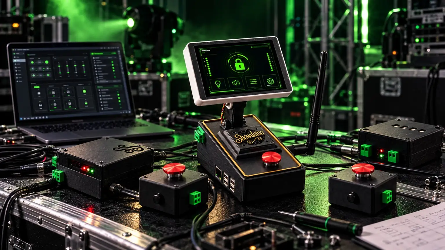
Showduino main control enclosure with a tilting Director touchscreen, illuminated green system display and gold Showduino front grille
PHYSICAL PRODUCT

The enclosure follows the architecture.

The current build puts the operator touchscreen, emergency control, service connections and P4-based runtime into a physical system that can be mounted, opened, wired and diagnosed like equipment.

Important: the touchscreen is the Director. It is not the authoritative Show Engine. The P4 remains responsible for runtime state and safety.
DIRECTOR

ESP32-S3 800×480 touchscreen

The Director is the operator-facing controller for live requests and system state.

  • RoleOperator requests and state display
  • Primary linkESP-NOW to Communications Controller
  • Runtime authorityNo — the P4 remains authoritative
COMMS CONTROLLER

Dedicated ESP32-S3 bridge

The Comms Controller transports wireless traffic to the P4 without making show decisions.

  • WirelessESP-NOW
  • P4 transportUART 115200 8N1
  • Show logicNone by design
SHOW ENGINE

Waveshare ESP32-P4-Module-DEV-KIT

The P4 is the centre of the live runtime: state, safety, cue dispatch, timeline execution, local storage and Showduino system services.

  • Comms UARTRX GPIO4 · TX GPIO5
  • I²C plug-in busSDA GPIO7 · SCL GPIO8 · 100 kHz
  • Onboard system audioES8311 codec (GPIO10 is audio WS, NOT status LED)
  • Emergency inputGPIO25
  • I²S system audioWS GPIO20 · BCLK GPIO21 · DATA GPIO22
  • Show pixelsGPIO23 (segmented)
  • Emergency signage pixelsGPIO24 (dedicated)
  • StorageSD card for projects/assets
  • Onboard C6Reserved / unused
REPAIRABLE BY DESIGN

What's inside Showduino?

Ordinary, replaceable development boards rather than a sealed custom-PCB controller. Each module has a specific role, service documentation and firmware. These are reference/vendor photographs; a few are representative of the board family rather than a verified photo of the fitted revision.

Waveshare ESP32-P4-Module-DEV-KIT black development board with Ethernet and USB ports CORE · EXACT MODEL

Waveshare ESP32-P4-Module-DEV-KIT

P4 Show Engine, mounted in the main Showduino enclosure beneath the tilting touchscreen. Runs cues, storage, system audio, local lighting and the Emergency latch.

Replacement: same P4 board revision, reflash Show Engine, fit microSD/configuration, verify UART, safety and audio before use.

Manufacturer image: Waveshare
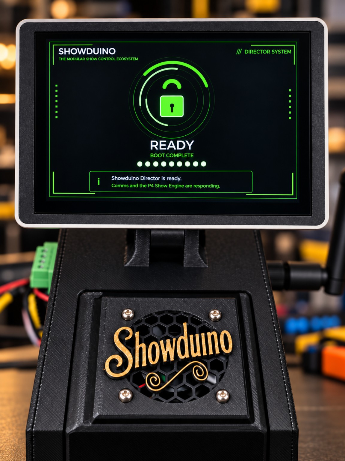
Showduino main control enclosure with adjustable operator touchscreen CORE · ACTUAL SHOWDUINO PRODUCT IMAGE

ESP32-S3 Director touchscreen

The 800×480 operator touchscreen is mounted above the main enclosure. It sends requests; the P4 remains authoritative.

Replacement: match ST7262/GT911 panel, flash Director firmware, restore peer configuration and test touch calibration.

Showduino project image, not an internal PCB identification photo
Representative ESP32-S3 N8R8 development board with pin headers CORE · REPRESENTATIVE BOARD FAMILY

Dedicated ESP32-S3 Communications Controller

ESP-NOW and Wi-Fi bridge. Connects the Director and specialist nodes to the P4 over UART GPIO17/18 → P4 GPIO4/5.

Replacement: confirm memory variant and pin map, flash Comms, restore pairing/MAC and Wi-Fi settings, test the P4 link.

Vendor photo (Waveshare-family S3), board revision may differ from fitted unit
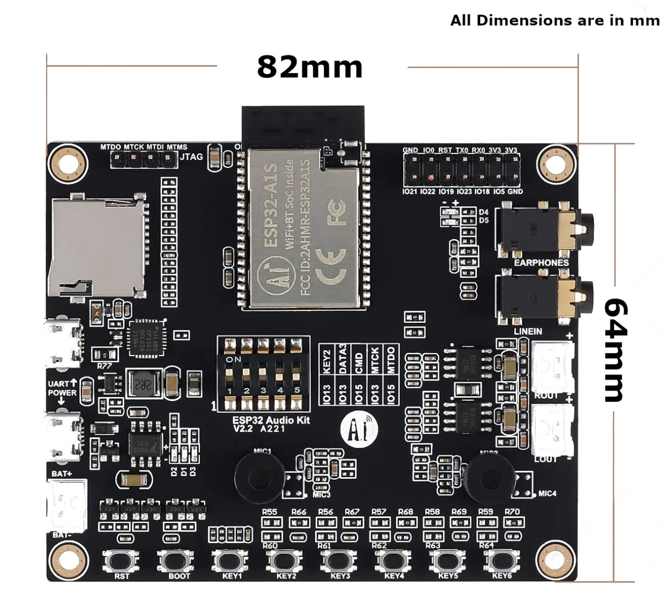
ESP32-A1S Audio Kit V2.2 board with audio jacks and microSD slot SPECIALIST · MODEL FAMILY

Ai-Thinker ESP32-A1S Audio Kit V2.2

Separate programme-audio Node with ES8388 codec and local SD WAV playback. Not the P4 system or PCM ambient audio.

Replacement: check A161/ES8388 variant (not AC101), flash Audio Node, restore media and validate speaker/emergency WAV.

Supplier image: Probots. Inspect board revision before ordering
Representative small ESP32-C3 board with integrated OLED display SPECIALIST · REPRESENTATIVE BOARD FAMILY

ESP32-C3 Super Mini OLED

Used for separate Pixel and wireless Emergency Node roles. Pixel data is GPIO2; OLED SDA5/SCL6. Emergency GPIO4 requires physical confirmation.

Replacement: flash the correct role firmware, assign a unique ID, set pixel count and retest Emergency input where relevant.

Vendor image: Allegro. Exact OLED PCB variant must be checked
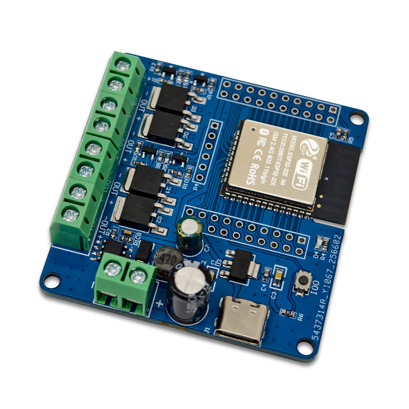
Representative blue ESP32 four channel MOSFET switching board SPECIALIST · REPRESENTATIVE HARDWARE

ESP32_MOS_X4 MOSFET Node

Four-channel low-voltage digital/PWM output module. The Showduino firmware is implemented; board mapping and physical outputs still need commissioning.

Replacement: verify the exact 303E32NMOS4 board and terminals before wiring; load test DC outputs only. Never connect mains directly.

Supplier image: HappyFish/marketplace; similar family, exact PCB not verified
Service note: replacing a board requires matching its voltage, memory, pinout and firmware; it is not necessarily plug-and-play. Disconnect power first, back up configuration and complete a fresh commissioning test. Showduino show-control Emergency logic is not a certified life-safety system.

ENCLOSURE DETAILS

Designed to be handled, wired and serviced.

The physical build is part of the system design, not decoration added after the electronics were chosen.

Control surface

Adjustable Director

The operator display remains easy to see and reposition without owning live runtime.

Connections

Pluggable field wiring

Serviceable connectors keep installation and troubleshooting practical.

Safety

Dedicated emergency input

Emergency control is physically obvious and logically separate from show effects.

SPECIALIST NODES

Output hardware follows the job.

Instead of forcing every effect through one generic box, Showduino uses specialist nodes that can be built, tested and diagnosed around the load they control.

RLY

Emergency Node

C3 wireless assert-only Emergency station with independent pixel capability. Main P4 button remains local.

MOS

MOSFET Node

Solid-state control for suitable low-voltage loads.

PIX

Pixel Node

Segmented addressable LED effects and emergency-white override.

AUD

Audio Node

Dedicated show audio playback beside P4 system sounds.

BUILT IN-HOUSE

Prototype, fit, wire, test.

The enclosure is iterated alongside the electronics. See the real build and the off-the-shelf boards below; exact revisions and firmware compatibility still matter.

01Print

Produce the enclosure and interface parts around the real hardware.

02Fit

Check clearances, mounting, cooling and service access.

03Wire

Install connectors and keep hardware roles physically understandable.

04Test

Commission the complete path from operator request to physical output.

EXPANSION

I²C without turning the P4 into a wiring mess.

The P4 exposes a defined plug-in bus for supported I/O and PWM expansion hardware.

MCP23017

General-purpose digital I/O expansion.

PCA9685

Multi-channel PWM/servo-style expansion.

TCA9548A

I²C multiplexing for repeated addresses or separate branches.

Current scope note: DMX is deliberately not part of the current Showduino implementation plan. The present focus is relay, MOSFET, pixel, audio, storage and runtime.

See how the hardware fits together.

The System Guide explains why these devices are separate and which one owns the live show.

Open System Guide